25 h11 c11 fits are either based on the hole feature or the shaft feature. H9 d9 d9 h9 h9 c9 h9.

Wobble or shake between mating parts noticed only on parts with short bearing length.
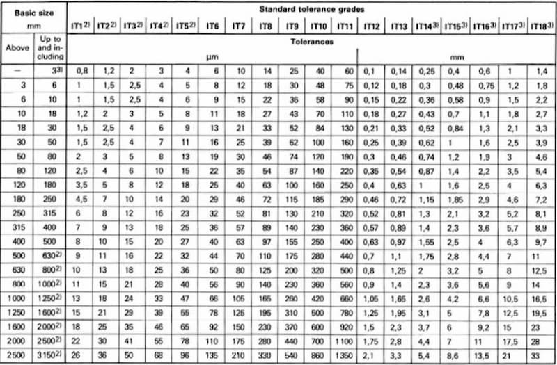
Press fit tolerance chart. This standard defines preferred limits and fits for press fits applications of non threaded cylindrical features preferred tolerances limits fits calculator rc lts this calculator will determine the preferred size and limit tolerances for running or sliding to interference locational fits per ansi b 4 1. H7 n6 for hole basis and n7 h6 for shaft basis. Using a 25 mm diameter a h7 n6 fit gives a max clearance of 0 006 mm and a max interference of 0 028 mm.
Interference fits are also known as press fits or friction fits. These types of fits always have the same principle of having a larger shaft compared to the hole size. Class ii free fit running fits with speeds of 600 r p m.
Or over and journal pressures of 500 lbs sqin or over. Wobble or shake between mating parts very slight. Part will turn and slide freely.
Class iii medium fit running fits under 600 r p m and journal pressures under 600 lbs sqin and for sliding fits. Wobble or shake between mating parts noticed only on parts with short bearing length. There are actual standards that define exactly what tolerances need to be to achieve various kinds of fits such as sliding fit press fit force fit free running fit and so on.
The standards include iso 286 ansi b4 2 and din 7172. Class iv transition fit tolerance chart for holes and bolts per mcdonald douglas design guide machining tolerances. Units given in inches.
Locational transition fits and tolerances are a compromise between clearance and interference fits for applications where accuracy of location is important but either a small amount of clearance or. Tolerances for housing bores axial displacement of outer ring remarks p7 n7 impossible generally impossible if axial displacement of the outer ring is not required. For heavy loads interference fit tight than k is used.
When high accuracy is required very strict tolerances should be used for fitting. M7 k7 possible axial. The tables in this section provide information about bearing tolerances seat tolerances and resultant fits these should enable you to determine easily the maximum and minimum values of fits when using iso tolerance classes for bearing seats and bearings with normal tolerances for the bore and outside diameter.
Technical data tolerances of regularly used hole fits excerpts from jis b 0401. In each column the upper figure is the upper dimensional tolerance and the lower figure is the lower dimensional tolera hole tolerance range class nce. A feature tolerance is defined by the basic size followed by the tolerance designation.
25 h11 or 25 c11 a fit is defined by the basic size followed by the tolerance of each component. 25 h11 c11 or separated with a dash ex. 25 h11 c11 fits are either based on the hole feature or the shaft feature.
Hole based fits should be preferred. This type of tolerance can be usable where any special requirements for accuracy in not essential but good for wide temperature variation heavy journal pressures and high running speeds. Some of the applications.
Multiple fits of shafts of production and piston machines parts rotating very rarely or only swinging. Some of the selected preferred fits. H9 d9 d9 h9 h9 c9 h9.